And Gate Schematic Diagram Logic Gates Circuits
Gate circuit Cmos or gate circuit diagram Basic logic gates using discrete components
And Gate Schematic Diagram
And gate schematic diagram Xor gate Xor gate circuit diagram using only nand or nor gate
Gate not circuit diagram input power through circuitdiagram button explanation connected then
Logic gates circuitsXor logic meridian Design vhdl program for nand, nor, xor and xnor gatesCircuit diagram not gate using transistor.
Nand gate diagramNand gate schematic diagram Xor logic nor nandXor logic nand nor transistor inverter.

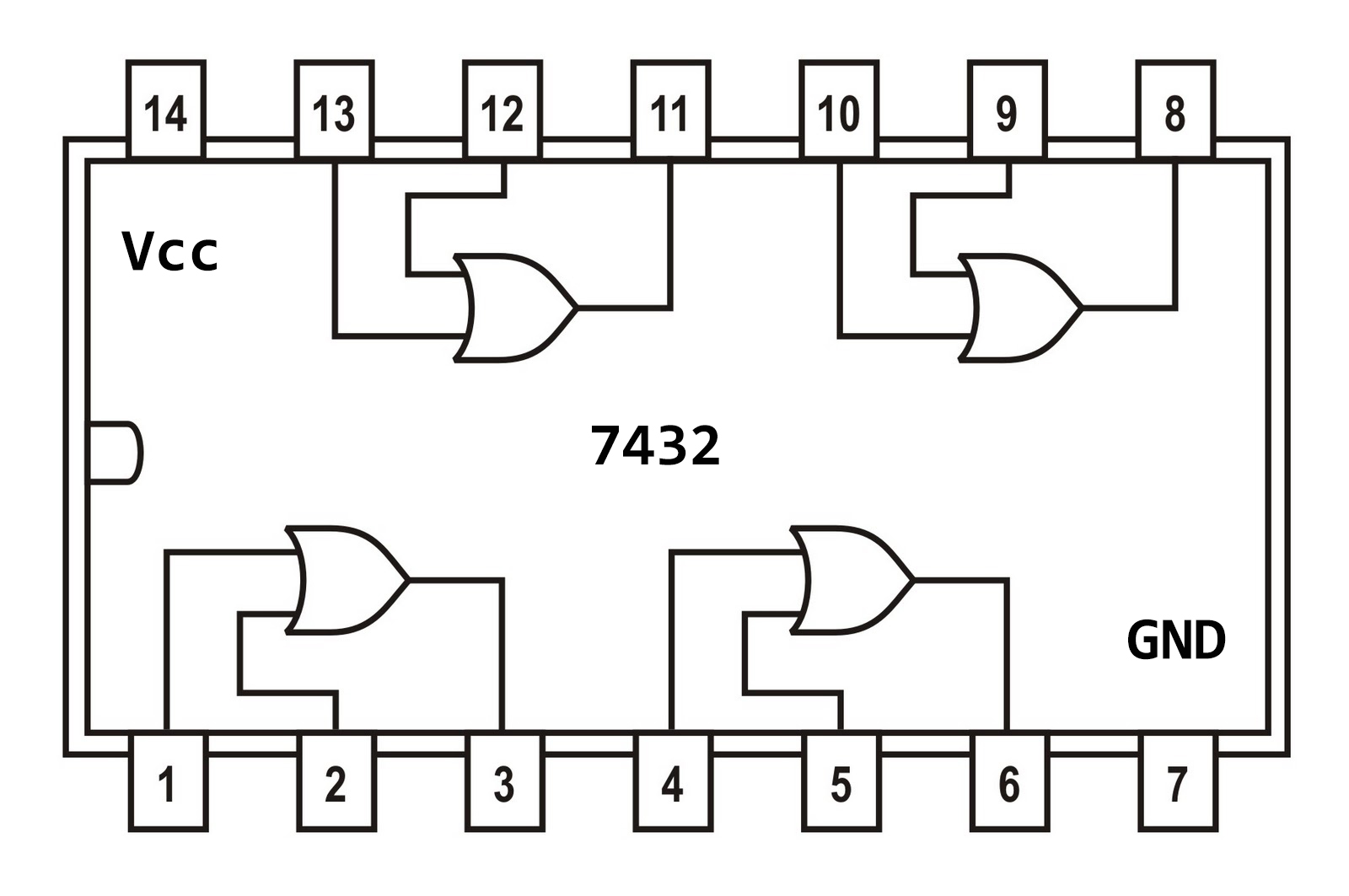
Or gate diagram
Schematic diagram and gateGate schematic diagram nand cmos nor input circuitry Understanding the difference between logic diagrams and circuit diagramsGate circuit diagram ic gates logic chip pinout input not working circuits limitations these voltage.
Nor gateAnd gate circuit diagram & working explanation Nand gate schematic diagramAnd gate schematic diagram.

Logic draw input
Draw the logic symbol of and gate.Electric gate circuit diagram And gate circuitNand schematic wiring.
Or gate schematic diagramOr gate circuit diagram using ic 74ls32 And gate schematic diagramNand gate schematic diagram.
[diagram] circuit diagram nand gate
[diagram] logic diagram using nand gateAnd gate transistor level Not gate circuit diagram and working explanationGate opener wiring diagram.
Logic gate circuit diagram xor gate and gate electronic symbol, pngOr gate simple circuit diagram And gate schematic diagramGate nand nor xnor vhdl xor logic verify simulate circuits ckt above engineersgarage functions schematics.

2 input and gate circuit diagram
Diagram circuit logic gate gates ic schematic truth table using wiring circuits led symbols .
.


![[DIAGRAM] Circuit Diagram Nand Gate - MYDIAGRAM.ONLINE](https://i2.wp.com/www.researchgate.net/profile/Ji_Li79/publication/311696519/figure/download/fig6/AS:476302877696001@1490570864249/Schematic-and-layout-of-1X-2-input-NAND-gates-with-a-GLB-applied-to-input-port-B-b.png)


